
Published by LogicHobbyist Automation Lab — A comprehensive, hands-on guide for engineers, system integrators, and enthusiasts. From basic theory to implementation and troubleshooting.
1. Introduction & Core Concepts
Modbus, developed by Modicon (now Schneider Electric) in 1979, is the most widely used industrial communication protocol. Its primary strength is its simplicity: it is an open, royalty-free standard that is easy to understand and implement. At its heart, Modbus allows a single “master” device to read data from and write data to multiple “slave” devices over various types of physical links, most commonly serial (RS-485) and Ethernet.
The Network Models
It’s important to distinguish the two main variants:
- Modbus RTU (Serial): Uses a strict Master/Slave model. The master initiates all communication, and slaves only respond when addressed. Only one master can exist on a single RS-485 network.
- Modbus TCP (Ethernet): Uses a more flexible Client/Server model. Multiple clients can connect to a single server, and the server can handle requests from multiple clients simultaneously.
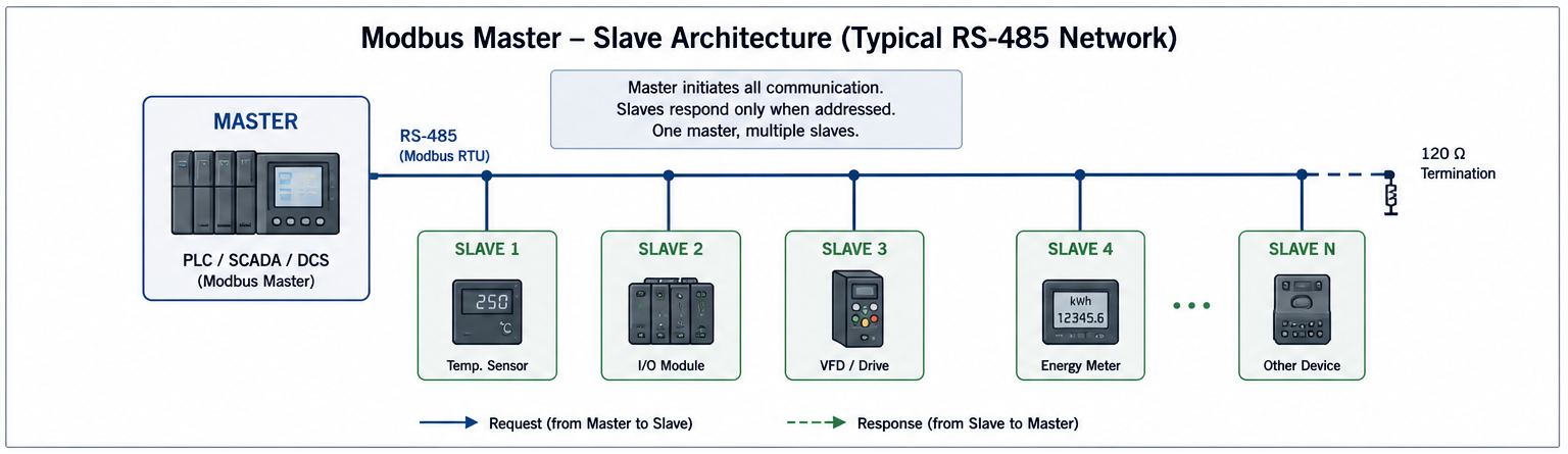
Figure : 1 Modbus Master-Slave Architecture
The Four Data Tables
Every Modbus device organizes its data into four standard tables. Before you can read or write data, you must know which table the information resides in.
| Table Name | Address Range (PLC) | Data Size | Access | Description |
|---|---|---|---|---|
| Coils | 00001 – 09999 | 1-bit (Boolean) | Read/Write | Digital outputs, relays, flags. |
| Discrete Inputs | 10001 – 19999 | 1-bit (Boolean) | Read-Only | Physical switches, sensor states. |
| Input Registers | 30001 – 39999 | 16-bit (Word) | Read-Only | Analog data: temperature, pressure, speed. |
| Holding Registers | 40001 – 49999 | 16-bit (Word) | Read/Write | Configuration, setpoints, accumulated values. |
The “PLC address” (e.g.,
40001) is 1‑based; the Modbus address in the packet is 0‑based hexadecimal.
For example, to read Holding Register 40001, a master sends a request for address 0x0000.
Some devices use 40001 = address 0, others use address 1. If you get garbage, shift by ±1.
2. Modbus RTU vs. TCP: A Detailed Comparison
While both protocols serve the same purpose, their underlying physics dictate their use cases. The Modbus Application Protocol (PDU) is identical; only the encapsulation method changes.
The Critical RTU Timing: T3.5 and T1.5
Unlike TCP, which uses a packet header for framing, Modbus RTU relies on silent intervals on the serial line to know when a message starts and ends. This is a common source of errors for beginners.
- T3.5 (Inter-Frame Delay): A pause of at least 3.5 character times indicates the end of one message and the start of the next.
- T1.5 (Inter-Character Delay): The maximum allowed gap between bytes within a single message. If exceeded, the receiving device discards the message.
If your RTU network is not working, verify your software’s serial settings correctly handle these timings.
Comparison Summary
| Feature | Modbus RTU (Serial) | Modbus TCP (Ethernet) |
|---|---|---|
| Architecture | Master/Slave (one master) | Client/Server (multiple clients) |
| Physical Layer | RS-232, RS-485 | Ethernet (IEEE 802.3) |
| Speed | 9.6 – 115.2 kbit/s | 10/100 Mbit/s+ |
| Typical Latency | 50–100 ms per device | Sub-millisecond |
| Error Checking | CRC-16 | TCP/IP stack + Ethernet CRC |
| Max Devices | 32 (without repeater) | Virtually unlimited |
| Cabling Distance | Up to 1200 m | 100 m per segment (extendable) |
3. The Packet Structure
Understanding the raw packet format is key to troubleshooting.
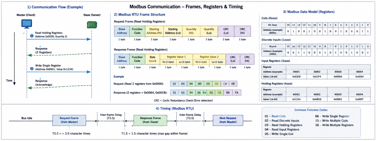
Figure : 2 Modbus RTU Frame Structure
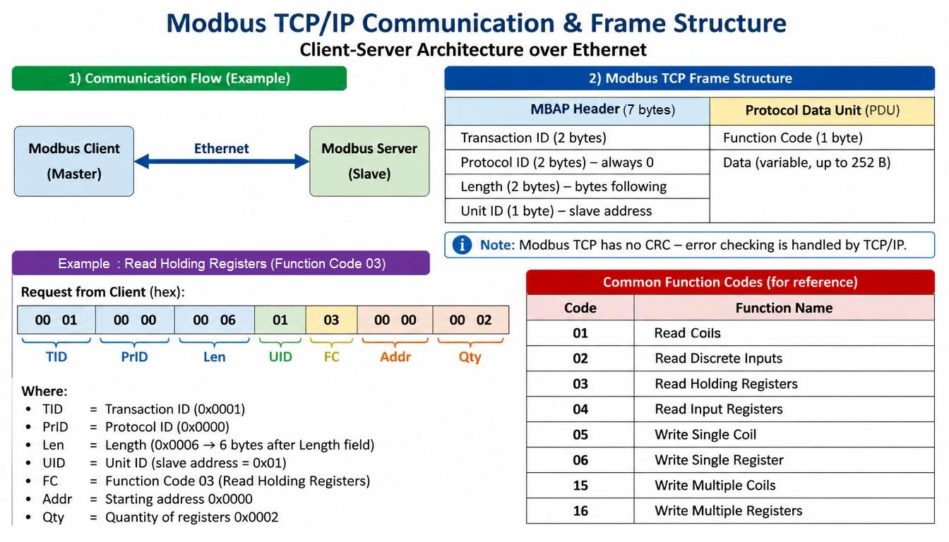
Figure : 3 Modbus TCP Frame (MBAP Header + PDU)
4. The Essential Function Codes
A device’s capabilities are defined by the function codes it supports. Quick reference:
| Code (Hex) | Function Name | Data Type | Access |
|---|---|---|---|
| 01 (0x01) | Read Coils | Digital Output | Read |
| 02 (0x02) | Read Discrete Inputs | Digital Input | Read |
| 03 (0x03) | Read Holding Registers | Analog Output/Setting | Read/Write |
| 04 (0x04) | Read Input Registers | Analog Input | Read |
| 05 (0x05) | Write Single Coil | Digital Output | Write |
| 06 (0x06) | Write Single Register | Holding Register | Write |
| 15 (0x0F) | Write Multiple Coils | Digital Output | Write |
| 16 (0x10) | Write Multiple Registers | Holding Register | Write |
5. A Practical Walk‑Through: From Theory to Implementation
Let’s move from theory to practice. Before you connect to real hardware, you can master Modbus using free, powerful software on your own PC.
Step 1: Know Your Tools
- Modbus Client (Master): QModMaster – open‑source, cross‑platform GUI.
- Modbus Server (Slave): ModbusPal (Java) or Modbux – both free.
Step 2: Set Up Your Test Bench
- Install both client and server simulators.
- In ModbusPal, create a slave with ID=1, add holding registers at addresses 0,1,2 with dummy values (e.g., 1234, 5678, 9999). Start the slave.
- In QModMaster, connect to Modbus TCP, localhost, port 502, slave ID=1.
Step 3: Read Your First Register
Use function code 03, starting address 0, quantity 3. Read – you should see the values from ModbusPal.
Step 4: Write Your First Register
Use function code 06, address 0, new value. Write – the value updates in both client and server.
6. Real Hardware for Practice – Cheap & Easy
Once you are comfortable with simulators, the next step is to talk to real physical devices. Here are three extremely affordable components to build your own Modbus RTU network (total under $30).
Any PC → RS‑485 adapter
Converts your computer’s USB port into a half‑duplex RS‑485 interface. Use it as a Modbus master (PC) to communicate with real slaves.
Load cell to Modbus RTU
Read weight values directly via Modbus. A perfect example of an Input Register (read‑only analog value).
8 relays + 8 opto‑isolated inputs
Write coils to turn relays ON/OFF and read discrete inputs from switches. The perfect slave for learning.
All three devices speak Modbus RTU over RS‑485. Connect them to the USB‑RS485 converter, then use QModMaster or a Python script to read weight, toggle relays, and read inputs.
7. Take It Further: Complete DIY Projects
Ready to build your own Modbus‑enabled hardware or a full HMI? These step‑by‑step tutorials show you how.
DIY Modbus I/O Board
Use an ESP32 or Raspberry Pi to create a custom Modbus slave with relays, inputs, and analog readings. Full code and wiring included.
Professional Graphical Interface
Build a cross‑platform Modbus master with real‑time trending, alarm logging, and register control using Python and PyQt5.
8. Practical Implementation: Bridging to Code
Python example using pymodbus (TCP)
from pymodbus.client import ModbusTcpClient

client = ModbusTcpClient('127.0.0.1', port=502)
if client.connect():
    result = client.read_holding_registers(address=0, count=1, slave=1)
    if not result.isError():
        print(f"Register 0 value: {result.registers[0]}")
    else:
        print(f"Error: {result}")
    client.close()
else:
    print("Connection failed.")
For C/C++, libmodbus is the standard library. For Python, pymodbus supports both RTU and TCP.
9. Learning Resources
- Official Specification: modbus.org
- Books: Modbus Protocol Engineering (depth), Modbus for IIoT Engineers (Python projects)
- Free Cheat Sheet: logichobbyist-industrial-modbus-cheatsheet.pdf – all function codes, register maps, wiring diagrams.
10. Troubleshooting Checklist & Common Pitfalls
– Check serial parameters (baud rate, parity, stop bits) match on all devices.
– Verify RS‑485 termination (120Ω resistors at both ends).
– Confirm Unit ID / Slave ID is correct and unique.
– Check power to all devices.
– 01 (Illegal Function): Slave does not support that function code.
– 02 (Illegal Data Address): Register/coil address does not exist.
– 03 (Illegal Data Value): Value written is out of range.
– CRC mismatch (RTU). Weak CRC implementation can corrupt data.
– Baud rate mismatch – produces random garbage.
11. When to Choose Which Protocol
- Long cable runs (>100 m, up to 1200 m)
- Electrically noisy environments (RS-485 is robust)
- Simple, low-cost installations
- Low bandwidth requirements
- High speed and low latency needed
- Already have Ethernet infrastructure
- Multiple clients accessing the same device
- Integration with IT systems and databases
LogicHobbyist Automation Lab – independent technical reference. Next reading: RS-485 Wiring Guide: Mastering the Physical Layer of Modbus