
The R4PIN08 is an ultra-compact, multi-function Modbus RTU expansion board. It is the perfect bridge for hobbyists looking to master industrial logic using Python. Its unique design allows you to select its physical role (Input vs. Output) using surface-mount jumpers (0603 0Ω resistors or simple wire bridges).
🔄 Configurable I/O Modes
The hardware personality is determined by the onboard jumpers (M1-M4). By soldering these bridges, you define the ratio of inputs to outputs as shown in the picture, the jumper uses a 0603 0ohm resistor(or a simple wire).
By soldering the M1–M4 jumpers according to the table below, the board’s personality changes instantly:
- 8DI / 8DO: Pure Input or Pure Output modules.
- 4DI-4DO: The most popular hybrid mode for Mini-PLC projects.
- 2DI-6DO / 6DI-2DO: Specialized configurations for custom control needs.
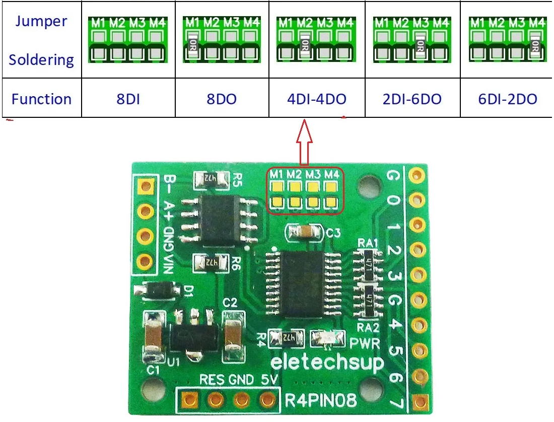
Figure 1: Jumper settings for 8DI, 8DO, or Hybrid modes.
🔌 Power & Wiring Interface
The R4PIN08 offers two power paths. Use VIN for standard industrial DC voltages (up to 25V) or the 5V pin for regulated logic power.
The board features two power interfaces for maximum flexibility. Note: Use only one at a time!
- Power Supply 1 (VIN/GND): DC 6-25V with Anti-reverse protection.
- Power Supply 2 (5V/GND): DC 4-5V (Warning: No reverse protection!).
- RS485 Port: Standard A+ and B- terminals.
- Factory Reset: Short the RES and GND pads for 5 seconds to restore factory defaults.
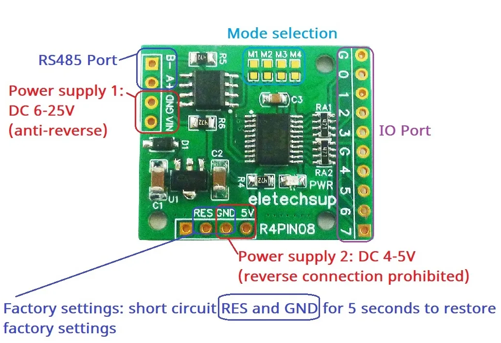
Figure 2: Power and RS485 terminal identification.
⚙️ Software Logic: NPN/PNP Switching
One of the most advanced features of this board is the ability to switch between Active Low (NPN) and Active High (PNP) logic without changing wires. This is done by writing values to the 0X00F5 (Input) and 0X00F6 (Output) registers.
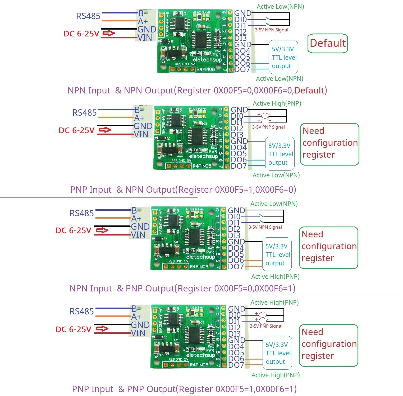
Figure 3: Wiring examples for NPN and PNP sensor types.
Unlike rigid industrial boards, you can change the input/output levels (Sinking/Sourcing) purely through Modbus registers:
| Configuration | Register 0X00F5 (Input) | Register 0X00F6 (Output) |
|---|---|---|
| NPN In / NPN Out (Default) | 0 | 0 |
| PNP In / NPN Out | 1 | 0 |
| NPN In / PNP Out | 0 | 1 |
| PNP In / PNP Out | 1 | 1 |
LOGICHOBBYIST PRO-TIP:
When switching from NPN to PNP, remember that you are changing how the module “expects” to see a signal. In NPN mode, it looks for a path to Ground. In PNP mode, it looks for a voltage signal. Always check your register settings before connecting sensitive sensors to avoid false triggers!
Always verify your jumper settings before powering the board. If you intend to use 3.3V/5V TTL signals from an Arduino or Raspberry Pi, ensure you have set the registers to match your logic level. For 24V industrial signaling, use an external opto-isolator to bridge the gap safely!