
10-Part Complete akYtec Industrial Automation Masterclass
This practical tutorial is part of an interconnected, step-by-step course designed to transition hobbyists and makers into professional B2B Industrial Integrators. Every lesson builds directly upon the hardware configurations, safety calculations, and visual programming rules established in the earlier sessions.
Transitioning logic code from a virtual simulation canvas to active physical silicon components requires an organized hardware verification flow. Handling physical automation equipment requires a different level of care than a standard hobbyist microcontroller. One misplaced connection trace or wiring loop can result in more than just a”magic smoke” smell; it can be dangerous to you and your equipment.
⚠️ Step 1: The Vital Nominal Power Verification Check
-
Before snapping the device onto your workbench test rail or stripping physical wire leads, look at the
manufacturer data sticker applied directly to the side of your physical housing. Connecting an incompatible
voltage line will cause catastrophic failure.
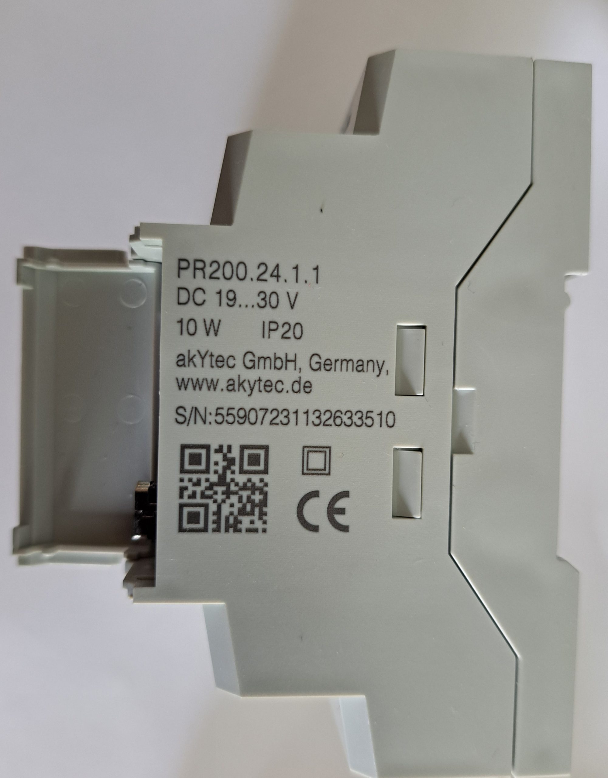
Figure 1: The product specifications label on the side of the PR200.24.1.1 chassis, indicating the 10W max power draw, IP20 safety rating, and the wide 19–30V DC input envelope.
- PR200-230.X.X (Mains Supply Profile): This model operates strictly on 230V AC mains potential. If you deploy this model, you must use a fused input plug line and remain extremely careful with exposed connection terminal screws. Always wire your line power inputs exclusively to terminals labeled L (Line) and N (Neutral).
- PR200-24.X.X (Low Voltage Supply Profile): This model operates strictly on a DC voltage power source. While the hardware specifications state that the device can operate dynamically within a wide input range of 19V to 30V DC, you should always stick strictly to the standard 24V DC baseline. Keeping your supply locked at a stable 24V ensures that your downstream field sensors, transmitters, and companion devices run within their optimal safety specifications.
- 🔒 The Golden Bench Rule (Pre-Plug Verification): Never plug a raw power connector straight into your programmable relay blind. Always take a step back and double-check both your connector polarity and the exact voltage potential before inserting the plug block into the terminal header. Doing this simple test takes less than a minute but saves you immense trouble and expensive replacement costs, especially when initializing a brand new wiring setup for the first time.
- Live Multimeter Interception: Set your digital multimeter (such as an ANENG M118A) to Auto DC Voltage Mode. Firmly press your test probes directly into the terminal wire slots of your loose green connector plug. Verify that the screen reads a stable, rock-solid 24.00V with the correct positive (+) and negative (-) matching terminal polarity before mating the connector plug onto the PR200 chassis.
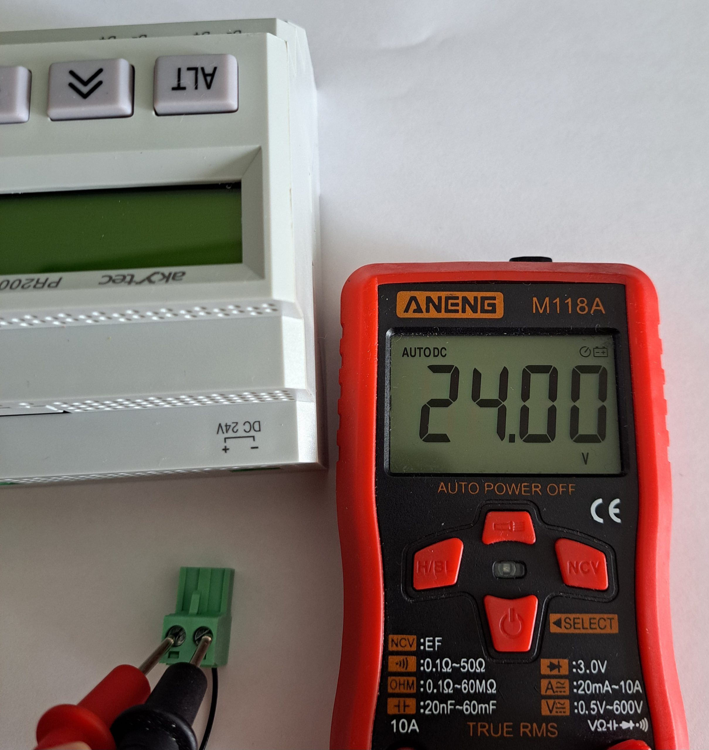
Figure 2 : Using the ANENG M118A multimeter to verify a perfect 24.00V DC power output and correct connector polarity before plugging it into the akYtec PR200.
🔌 Step 2: Preparing Your Test Bench Elements (Switches & LED Validation)
Now that our core target relay power rails are verified and stable, we will expand our physical test layout. To safely validate the SR latch logic program we constructed in Lesson 1, we will map two physical tactile switches and a status LED indicator to our I/O loop terminals.
- Gather Your Components: Prepare two momentary push-button switches, one standard diagnostic LED, an ANENG M118A multimeter, and a handful of solid-core jumper wires.
- Calculating the LED Safety Resistor: Industrial 24V loops require heavy current throttling
to protect delicate indicator semiconductors. Using Ohm’s Law, running a standard 20mA LED at 24V requires
careful calculation:
24V / 0.016A = 1500Ω (1.5kΩ).
To instantly double-check your safety thresholds across different operational voltages, utilize our custom LED Series Resistor Calculator tool. For this quick test layout, a standard 1.5k Ohm resistor keeps our diagnostic LED completely safe and bright enough.
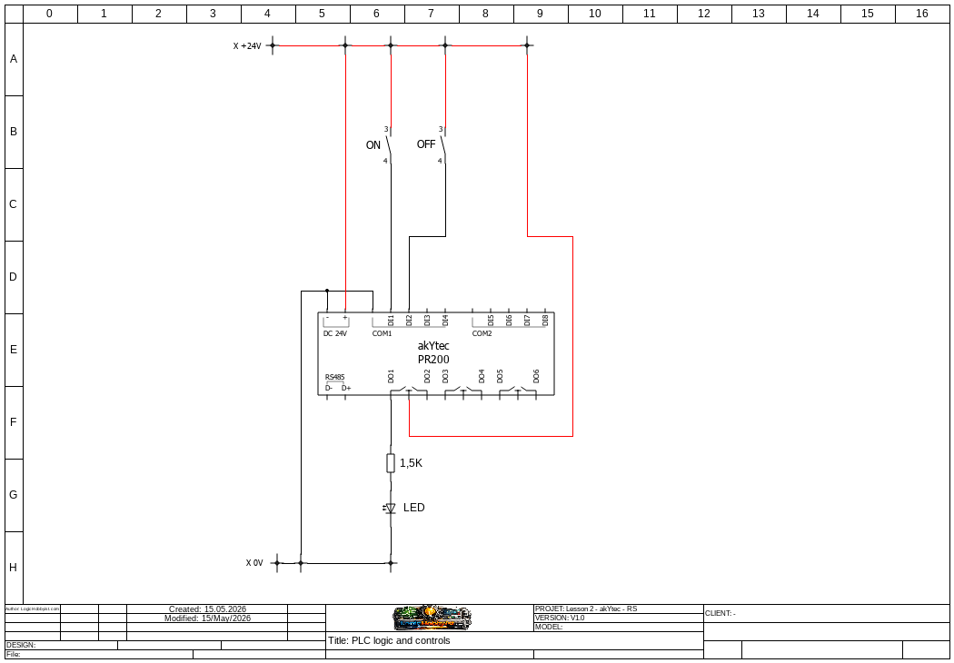
Figure 3: Electrical schematic wiring configuration of the PR200-24 inputs and output test loop.
🎨 Pro Drafter Notice
A comprehensive, step-by-step drafting tutorial will be published soon on how to deploy the free, open-source QElectroTech software suites to trace your professional B2B electrical blueprint schematics.
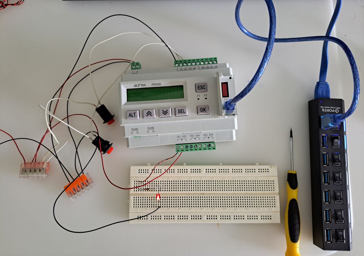
Figure 4: The finalized physical bench wiring connection showing the test switches securely integrated.
💻 Step 3: Hardwiring Hardware & Windows COM Port Identification
With your loop paths securely arranged, we can now establish the physical control communication connection lines to our PC host workspace.
- Firmly mate your pre-tested, 24V power supply block connector plug straight into the main PR200 power rails slot.
- Open the side protective utility hatch cover on the relay chassis and plug the micro-USB cable directly into the programming port, then plug the opposite end into an open USB port on your PC.
- The Connection Verification Trick: Launch your Windows 10/11 Device Manager and scroll down to expand the Ports (COM & LPT) branch index tree. If you are unsure which port is yours, execute a fast sequence check: disconnect the USB wire, watch which index line disappears from the list, then reconnect it. The line that reappears is your active communication interface port.
- Double-click your active line to check its inner port configuration settings. Ensure the operational parameter details match cleanly to ensure error-free data packet transfers.
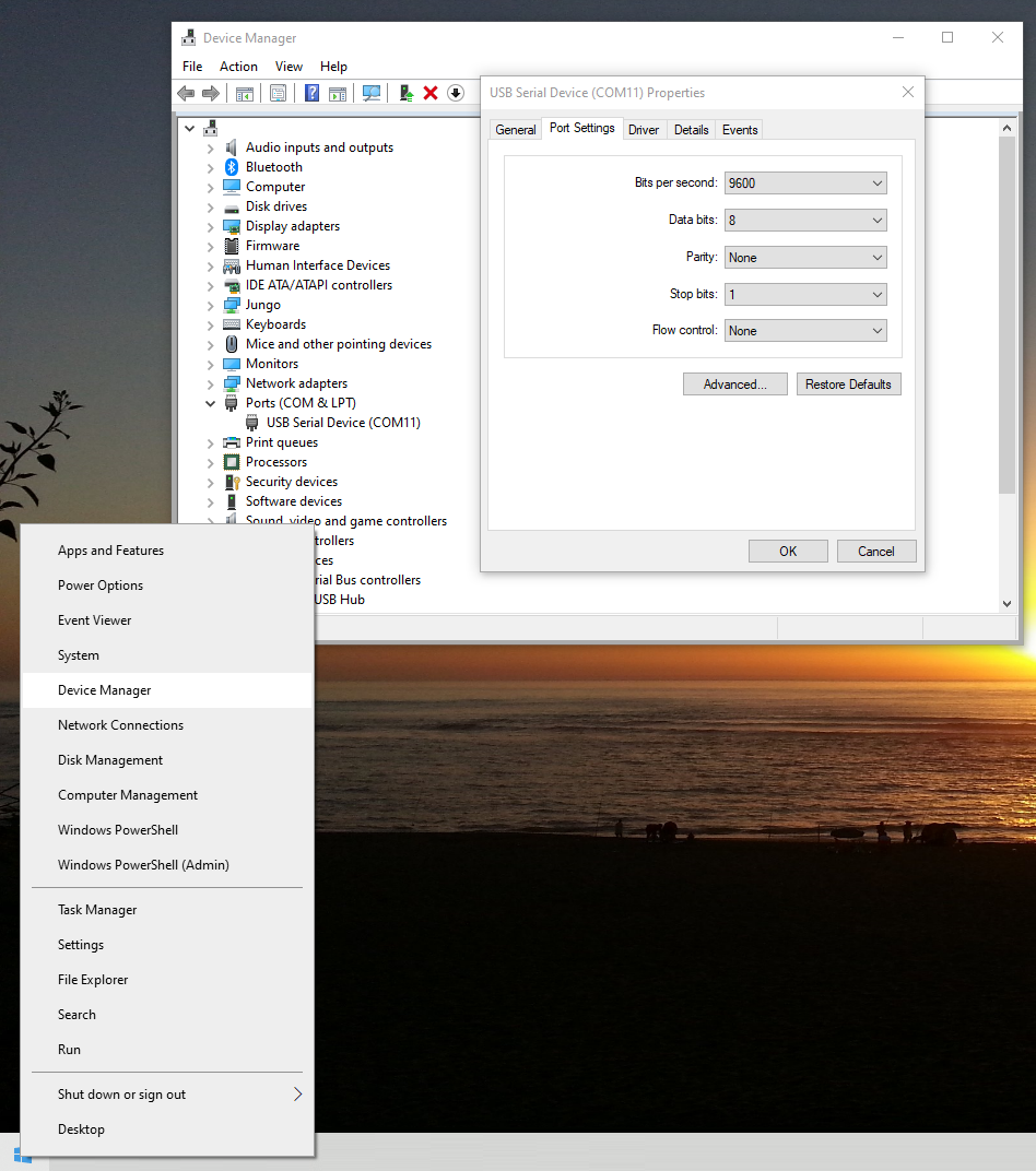
Figure 5: Inspecting the Windows Device Manager Virtual COM Port baud configuration mappings.
📡 Step 4: Configuring ALP Communication Paths
Now, we map the software environment variables straight to our recognized virtual hardware communication port link inside the akYtec ALP software workspace.
- Open your ALP project workspace sheet. From the upper file navigation taskbar menu options block, select Device ➔ Port Settings.
- Change the Connection Type toggle line selection from Ethernet/Wi-Fi directly to Serial Port.
- Click directly over the parameter field option marked”None” right across the Serial Port row, select your verified hardware COM Port Number, and verify that all matching transmission metrics line up smoothly before clicking OK.
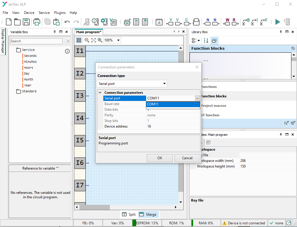
Figure 6: Configuring the internal Serial Port communication parameters inside akYtec ALP.
🎯 Success Milestone Indicator: Look closely down at the lower right-hand corner edge of your ALP application workspace frame window. If your parameters are applied correctly, your baseline status string text will instantly transition from reading “Device is not connected” to displaying a clean, live connection notification: “PR200.24.1.X”.
⚠️ CRITICAL PRO INTEGRATOR NOTE (The Source Control Rule)
An essential operational characteristic of the akYtec PR200 ecosystem is that you can compile and upload code blocks to the device, but you cannot download an application back from the PLC flash memory into your PC (unlike platforms like Beckhoff TwinCAT or Siemens TIA Portal).
Because your physical controller acts as a one-way terminal, you must maintain well-organized master backup directories of your local source files. If your module suffers sudden field failure or physical damage, your hard work will be safe.
- Version Controls: Save your file schema as a fresh copy each time you implement
critical logic alterations. Append short, clean descriptive text blocks that include the exact
deployment date and timestamps (e.g.,
PR200_Latching_v1_2026_05_15.owle). - The Readme Strategy: Keep a plain text document named
README.txtdirectly inside your primary local project folder. Record your change history logs sorted sequentially by date, detailing exactly what errors were fixed or what variables were added. Taking a few unhurried minutes to build this habit will protect your project assets like a true engineering professional.
⚡ Step 5: Transferring the Application File & Firmware Overrides
With your communication link live, you can execute your file flash sequence using three different methods based on your preference:
- Click the Write to Device symbol located on your top shortcut menu dock (represented by a pen icon floating directly over an integrated hardware card layer).
- Navigate to the top workspace drop-down navigation row options block and select Device ➔ Transfer application to device.
- Execute the fast standard keyboard developer shortcut command string: Ctrl + F7.
🚨 CRITICAL FIRMWARE FLASH WARNING
Because akYtec introduces code stability optimizations frequently across their platform releases, a pop-up confirmation alert container may appear warning you that the device hardware firmware requires an upgrade.
You must accept this prompt to proceed. Once the flash progression begins, do not touch, manipulate, or adjust your workbench wire lines, USB connection cables, or main power inputs. Any sudden drop in operational current or signal loss during this critical flash sequence will brick the inner non-volatile system structures, rendering your physical relay permanently inoperable.
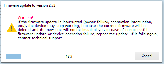
Figure 7: Handling the automated firmware system modernization prompt and processing files safely.
During this automated compilation cycle, the ALP programming framework will translate your logic sheets to target the latest file specifications, automatically backing up your original baseline files into an archive directory inside your project tree.

Figure 8 : Reviewing the active application binary payload block file transfers to the PLC module memory core.
🧪 Step 6: Real-World Bench Execution & Physical Verification
Once the download progress bar closes and the hardware cycles back online, your PR200 unit functions as an active, standalone industrial automated control module. We can now verify our SR logic loop on physical hardware components:
- Press down once on your physical tactile switch connected directly to digital terminal input I1. This injects a high 24V signal pulse to the internal Set pin of our latch block.
- You will instantly hear a crisp, mechanical “Click” sound from the interior casing. This confirms that the internal electromagnetic coil has pulled down, closing physical relay contact channel Q1.
- The external test bench LED indicator line will turn ON immediately. Because our visual code holds the high state inside the internal memory registers, the output LED stays illuminated even after you release the I1 start button.
- To reset the logic memory, press the physical switch connected directly to digital input I2. The latch immediately drops, the output channel opens up, and your diagnostic LED turns completely off.
Figure 9 : The live hardware layout test in action, demonstrating the closed Q1 loop successfully driving our diagnostic LED high.
Ready to Scale Up with Interface Displays?
You have successfully wired your power rails, configured your virtual COM interface drivers, and validated your logic loops on physical silicon. Now, let’s step up to human-machine interaction.