
Published by LogicHobbyist Automation Lab — From blinking an LED to switching industrial solenoids. Learn how to use NPN and PNP transistors as reliable electronic switches with real‑world examples and interactive simulation.
1. Why Use a Transistor as a Switch?
A microcontroller (like Arduino, ESP32, or Raspberry Pi) can only source or sink a few milliamps (typically 20‑40 mA). To control a 12V or 24V load that draws hundreds of mA – or even amps – you need a transistor switch. Compared to relays, transistors are faster, silent, and last virtually forever when used correctly. Their main limitation: they are usually DC‑only and do not provide galvanic isolation (unless paired with an optocoupler).
2. NPN vs PNP: Low‑Side vs High‑Side Switching
Two common bipolar junction transistor (BJT) types are used for switching: NPN and PNP. For microcontroller projects, the NPN low‑side switch is the most straightforward.
| Feature | NPN (Low‑Side Switch) | PNP (High‑Side Switch) |
|---|---|---|
| Load connection | Load between positive supply and collector | Load between emitter and ground |
| Base activation | Positive voltage (e.g., 3.3V/5V) | Ground (0V) |
| Common in microcontrollers | ✅ Very common (e.g., BC547, 2N2222) | ❌ Requires level shifting often |
| Industrial equivalent | Sinking output (NPN sensor) | Sourcing output (PNP sensor) |
For microcontroller‑controlled loads, always start with an NPN low‑side switch. It is simpler, cheaper, and well‑supported.
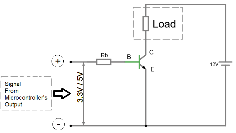
Figure : 1 NPN low‑side switch circuit diagram (load between +V and collector; emitter to ground; base via resistor to GPIO)
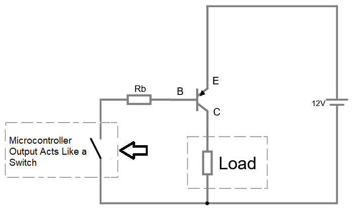
Figure : 2 PNP high‑side switch circuit diagram (load between emitter and ground; base pulled low via resistor)
3. The Three Operating Regions
For a reliable switch, you must drive the transistor into saturation (fully on) or cutoff (fully off). The active region (linear) is used for amplifiers – not for switching.
- Cutoff: VBE < 0.6V \), \( I_C \approx 0 \) – transistor acts as an open switch.
- Active region: \( I_C = \beta \times I_B \) – used for linear amplification (avoid for switching).
- Saturation: \( V_{CE} \) drops to ~0.2V, \( I_C \) is limited only by the load – transistor acts as a closed switch.
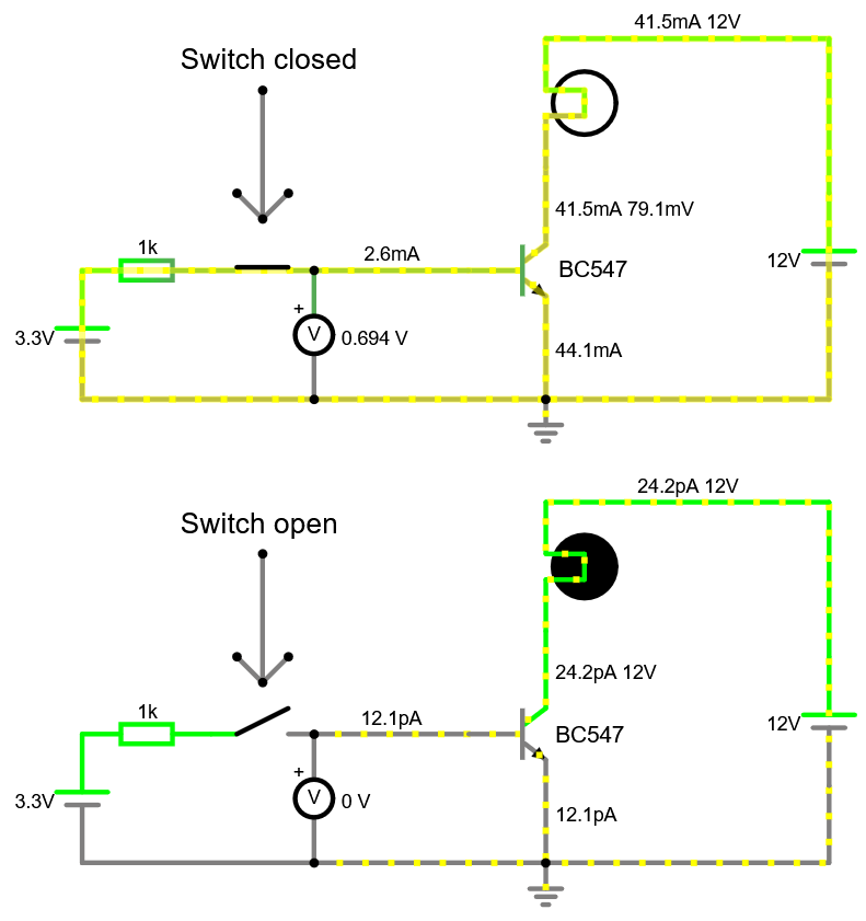
Figure : 3 Simulation screenshot – switch open (cutoff) vs switch closed (saturation).
4. Complete NPN Low‑Side Switch – Component by Component
A practical circuit has five essential parts:
- Microcontroller GPIO (3.3V or 5V, max 20‑40 mA).
- Base resistor (RB) – limits base current to safe values and ensures saturation.
- NPN transistor – e.g., BC547 (low power, up to 100 mA), 2N2222 (up to 600 mA), TIP120 (Darlington, up to 5A).
- Load – relay coil, solenoid, LED strip, small DC motor.
- Flyback diode – mandatory for inductive loads (see Section 6).
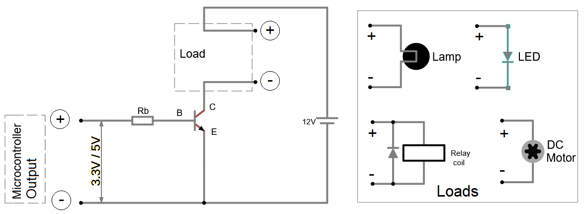
Figure : 4 Labelled NPN switch schematic with base resistor, load, and flyback diode.
5. Calculating the Base Resistor – Step by Step
To saturate the transistor, we use the rule: IB = (IC / βmin) × Safety Factor. For switching, a safety factor of 1.3 (30% overdrive) is typical.
Formula: RB = (VGPIO – VBE(sat)) / IB
where VBE(sat) ≈ 0.7V for silicon BJTs.
🧮 NPN Base Resistor Calculator
⚡ Use the nearest standard resistor value (E12 series). For example, 1kΩ, 1.2kΩ, 1.5kΩ, 2.2kΩ, etc.
For a more advanced calculator (including power dissipation and colour code), see our Industrial Automation Toolbox and the dedicated Base Resistor Calculator.
6. Flyback Diode – Why It’s Mandatory for Inductive Loads
When you switch off a relay coil, solenoid, or motor, the collapsing magnetic field generates a high‑voltage reverse spike (often >100V). This spike can instantly destroy your transistor. A flyback diode (also called freewheeling diode) placed in parallel with the inductive load (cathode to positive supply) clamps the spike.
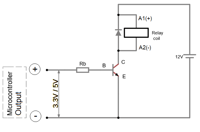
Figure : 5 Flyback diode connected correctly – cathode to +V, anode to collector (load side).
7. Driving Higher Loads – Darlington Pairs and MOSFETs
If your load requires more than 500‑800 mA, a single BJT may overheat. Options:
- Darlington pair (e.g., TIP120) – two transistors in one package, current gain >1000. Drawback: higher saturation voltage (~1.2V).
- Logic‑level MOSFET (e.g., IRLZ44N) – voltage‑controlled, very low on‑resistance, no base current. Ideal for PWM and high currents.
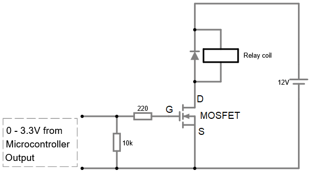
Figure : 6 MOSFET low‑side switch circuit – gate to GPIO with a pull‑down resistor, no base resistor needed.
8. Troubleshooting Common Issues
- Transistor does not turn fully on: Increase base current (reduce RB). Ensure GPIO voltage is correct.
- Transistor gets hot even with small loads: You may be operating in the active region. Check VCE when “on” – it should be < 0.5V.
- Load turns on without GPIO signal: The base may be floating – add a 10kΩ pull‑down resistor from base to emitter.
- Oscillation / erratic switching: Long wires? Add a 1kΩ resistor in series with the base close to the transistor.
9. Interactive Falstad Simulation – See It Live
The circuit below shows an NPN transistor switching a 12V lamp. Press the “switch” (simulates a GPIO) and watch the lamp turn on. The simulation also shows current and voltage values.
You can also download the circuit file: using-transistors-as-power-switches.txt (right‑click → Save Link As). Import it in Falstad via File → Open File.
10. Advanced Topics – Galvanic Isolation and Industrial I/O
For noisy industrial environments or when you need complete electrical isolation between a microcontroller and a high‑power load, use an optocoupler.
If you are designing a PLC output, understanding sourcing (PNP) vs sinking (NPN) is essential:
11. Summary – Quick Reference Card
- ✅ Choose NPN low‑side switch for microcontrollers.
- ✅ Calculate base resistor with a 1.3x safety factor.
- ✅ Always add a flyback diode for inductive loads.
- ✅ Use a multimeter to verify saturation: \( V_{CE} < 0.5V \).
- ✅ Add a 10kΩ pull‑down resistor if the base floats.
LogicHobbyist Automation Lab – independent technical reference. Next reading: Industrial Automation Toolbox – every calculator in one place