
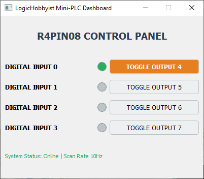
Figure 1: The custom-built PyQt5 operational interface for the R4PIN08 module with Input-1(pin-4 on the board) and Output-1 active.
🧭 Course Roadmap
Follow these steps to transform your R4PIN08 hardware into a software-driven controller.
Welcome to the LogicHobbyist Masterclass. In this guide, we bridge the gap between simple hardware and professional software. By the end of this page, your computer will act as a PLC, controlling physical I/O through a custom-built Graphical User Interface (GUI).
Step 1: Preparing the Engine (Python)
Visit python.org and download the latest stable release. During the installation process, you must check the box “Add Python to PATH”. This step is mandatory; without it, your terminal will not recognize Python commands.
For this masterclass, we are utilizing the Python Install Manager to ensure a streamlined setup. However, before we execute any code, we must apply the “Industrial Defense” mindset.
🛡️ Security First: Scan Before You Execute
As we discussed in our article on Why VirusTotal is the First Line of Defense, you should never trust a download blindly.
Upload your installer to VirusTotal before running it. Remember: installing software opens a permanent “gate” into your system. Beyond this initial scan, ensure your system has an up-to-date Antivirus to monitor for threats during future software updates or background processes.
Installation & Conflict Resolution
Once you execute the installer, it will begin downloading the necessary packages. The manager is designed to be intelligent: if it detects an existing Python version that could cause a naming conflict, it will prompt you to uninstall the older version.
If the installer asks you to clean up your environment, follow these steps:
# 1. To open the Command Prompt, Press Win + R and type:
 cmd

# 2. To show which version is currently tied to your PATH, type:
 python --version

# 3. Go to Settings > Apps (the installer may open this for you automatically) and uninstall the version found in step 2.

# 4. Follow the prompts until the removal is complete.
When the installer finishes, go back to your Command Prompt and type python –version again. You should see the brand new version confirmed! Yeah! You are officially ready for Step 2.
Step 2: Creating the Virtual Sandbox (venv)
A Virtual Environment (venv) ensures that your PLC libraries don’t interfere with other projects. It creates a local “bubble” for your code.
Think of a Virtual Environment as a dedicated “clean room” for each engineering project. While your system-wide Python remains untouched, each sandbox contains its own copy of the interpreter and libraries.
🛡️ Why the Sandbox is Critical
- Security Isolation: If a package is ever compromised, it remains trapped within that project’s folder, preventing it from corrupting your global system.
- Zero-Conflict Development: You can create unlimited projects, each with different versions of the same library, without them fighting for control.
- Deployment Ready: Keeping dependencies separate makes it significantly easier to compile your project into a standalone .exe file later, as you only package the exact tools that specific project needs.
Let’s Create Your Environment!
Follow these steps in your terminal to create your first isolated workspace:
# 1. Create the Directory:
mkdir my_mini_plc

# 2. Move to your project folder and type:
cd my_mini_plc

# 3. Build the Sandbox: Execute the venv module and wait it to finish:
python -m venv venv

# 4. Activate it (Windows), Tell your terminal to use this local environment:
.\venv\Scripts\activate

# 5. You should see something like:
(venv) C:\Path_to_your_project_folder\my_mini_plc

# 6. To make sure your venv is correctly activated
(sometimes it fails but shows (venv) as activated ) execute the following:
pip list

# 7. The result will be a short list something like this:
Package Version
------- -------
pip     26.1.1
Yeah! Once activated, you will see (venv) appear before your command prompt. This is your signal that you are safe to install libraries and move to Step 3.
Step 3: The “Hello World” of Industrial Logic
Now that our sandbox is active, we need to install the “translator” that allows Python to speak the Modbus language and the PyQt5 library to build a GUI instead of just a terminal. We will use minimalmodbus because it is clean, fast, and reliable.
1. Install the Library
# Install required libraries:
pip install minimalmodbus PyQt5
2. Identify and Verify Your Hardware Port
Before writing code, we need to know exactly which “door” (COM Port) your computer assigned to the USB-RS485 converter. Follow these practical steps to locate it:
- Right-click the Windows Start button and select Device Manager from the power user menu.
- Scroll down and click the arrow next to Ports (COM & LPT) to expand the sub-list. Look for an entry like mine here: USB-SERIAL CH340.
- 🔍 The LogicHobbyist Verification Trick: If you see multiple COM ports listed and aren’t sure which one is your converter, simply unplug the USB-RS485 stick. Watch the list—the correct COM port will instantly disappear. Plug it back in, and it will reappear. That confirms your hardware port!
- In my specific case, it shows up as COM9 as seen in the screenshot below.
- Double-click your COM device from the list, and select the Port Settings tab. Take note of your hardware configuration (Baud Rate, Data bits, Parity, Stop bits). We will need these exact values for our Python script.
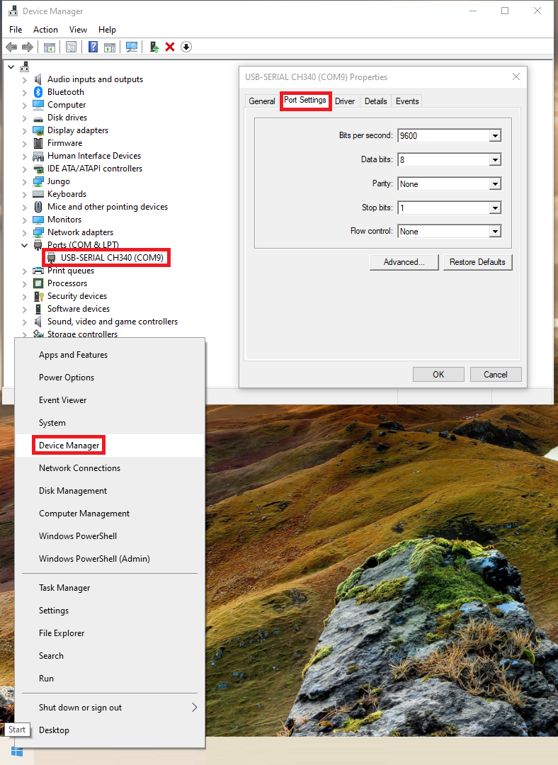
Figure 2: Identifying the CH340 USB-to-Serial converter (COM9) and inspecting Port Settings.
Once you have noted down your COM number and verified the settings, close the properties dialog box and close the Device Manager. You are ready to drop this port directly into your script!
3. The First Output Test: Voltage Validation
Since our compact R4PIN08 module uses solid-state TTL logic outputs rather than loud mechanical relays, we will not hear a “click.” Instead, we will use a digital multimeter to measure the actual voltage change when Python triggers the output.
⚠️ Multimeter Configuration Rules:
- Selector Safety: Always unplug your test leads from the circuit before turning the multimeter’s central selector switch.
- Scale Selection: Turn the multimeter ON and set it to the 20V DC scale. We cannot use the smaller 2V scale because our module outputs a 3.3V logic high signal.
- Power Warning: Keep the entire system powered OFF while plugging in and preparing your test leads.
The Physical Wiring Connections
Wire your USB-to-RS485 converter, the power rails, and the multimeter leads exactly as follows (configured for 4DI / 4DO mode):
| Connection Type | Wire Color | USB adapter Pins / Target R4PIN08 Pins |
|---|---|---|
| Power Rail (+) | Red | USB +5V to VIN |
| Power Rail (-) | Black | USB GND to GND |
| Modbus Data A | Brown | USB A to A+ |
| Modbus Data B | Blue | USB B to B- |
| Multimeter (+) | White | Red Crocodile Clip to Output 4 (First DO pin) |
| Multimeter (-) | Gray | Black Crocodile Clip to G (GND pin) |
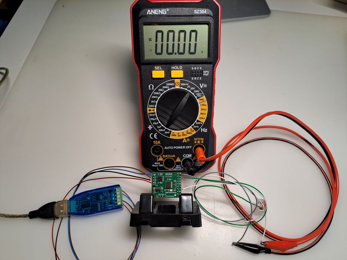
Figure 3: Measuring the 3.3V DC digital output state using an ANENG SZ304 multimeter.
The Test Script (test_output.py)
Create a new file in your project folder named test_output.py. Copy the code
below, making sure to use the COM port you identified in the previous step (e.g., 'COM9').
import minimalmodbus
import time

# Initialize our Mini-PLC at COM9, Slave Address 1
plc = minimalmodbus.Instrument('COM9', 1)
plc.serial.baudrate = 9600
plc.serial.timeout = 0.2

try:
    print("Sending command: Turning Output 4 ON...")
    # In 4DI/4DO mode, my module is mapped:
    # from 0 to 3 as inputs
    # from 4-7 as outputs
    # you have to check your module's datasheet if you have other version, that can be mapped differently.
    plc.write_bit(4, 1, functioncode=5) # 4 means the first output, and 7 is output 4
    print("Check Multimeter: It should read approximately 3.3V DC!")

    time.sleep(5) # Leave it on for 5 seconds

    print("Sending command: Turning Output 4 OFF...")
    plc.write_bit(4, 0, functioncode=5)
    print("Check Multimeter: It should drop back to 0.00V!")

except Exception as e:
    print(f"Communication Failed! Verify your A/B lines and COM port: \n{e}")
4. Executing the Script & Verifying Success
With your hardware safely wired and the multimeter in place, it is time to execute our test script. Open your command line interface, ensure your virtual sandbox is active, and navigate directly to your project directory.
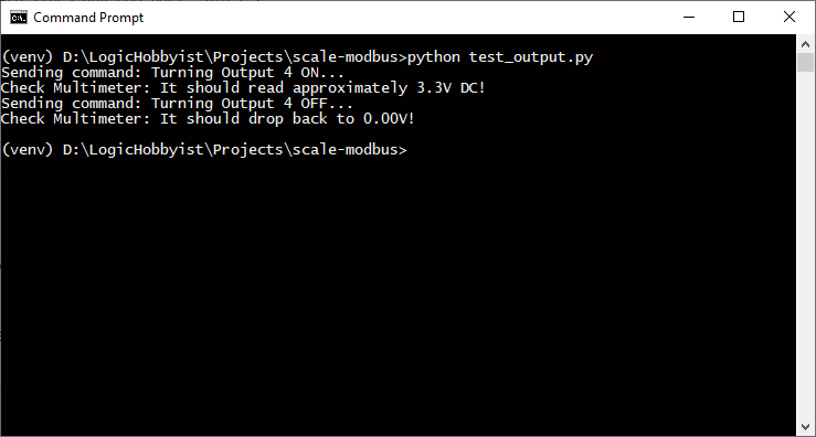
Figure 4: Running the test script inside the activated virtual environment directory.
As shown above, your terminal path should clearly display your active sandbox badge: (venv) D:\LogicHobbyist\Projects\scale-modbus>. Type python test_output.py and hit Enter.
📡 Visual Confirmation Checklist:
- Diagnostic Blink: The moment you run the script, the TX/RX LEDs on both the USB-to-RS485 module and the R4PIN08 module will blink quickly. This quick flash is an immediate sign of success—it proves your computer is officially communicating with the hardware over Modbus.
- Multimeter Jump: Watch your multimeter display. The moment the script sends the HIGH command, the voltage will instantly leap to approximately **3.3V DC** and hold for 5 seconds before dropping back to zero.
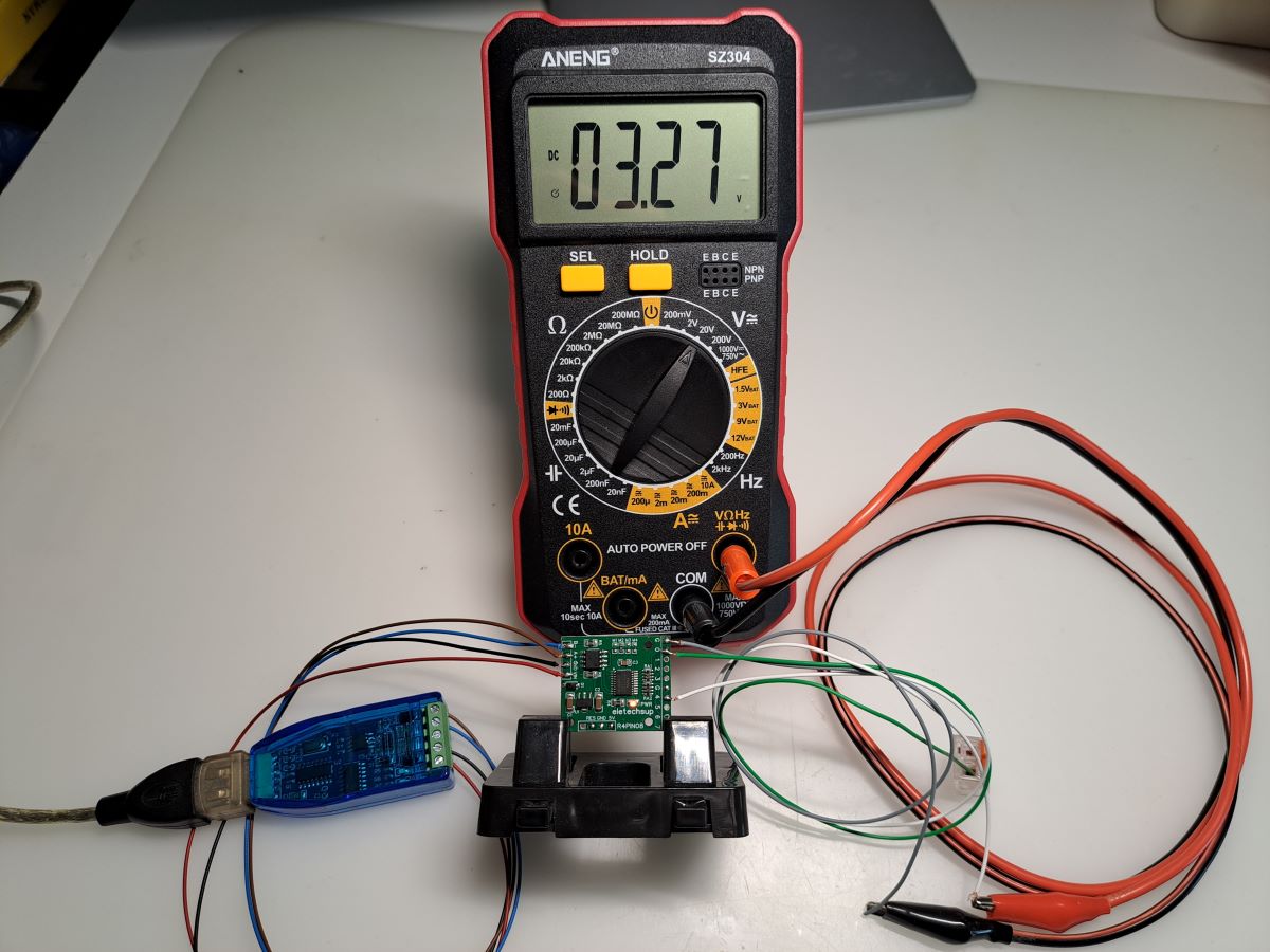
Figure 5: Active test environment verifying the 3.3V logic high output on your multimeter.
If your indicators flashed and your meter read a solid 3.3V, your low-level data link is bulletproof. Your hardware is verified, your script is talking, and you have officially completed the low-level foundation. We are now ready to jump into **Step 4** and design our graphical HMI panel!
LOGICHOBBYIST PRO-TIP:
In industrial programming, we never trust a “Write” command alone. After sending write_bit(0, 1), a pro-level script will immediately follow up with a read_bit(0) to verify the hardware actually changed state. This “Close-Loop” logic is what prevents system failures in real-world plants.
Step 4: Building the PyQt5 Industrial Dashboard
Now, we give our Mini-PLC a professional face. We will build a graphical user interface window that displays the live status of our 4 Digital Inputs as Visual LEDs and provides interactive Toggle Buttons for our 4 Digital Outputs. To achieve this, make sure the UI framework is installed inside your active sandbox:
pip install PyQt5
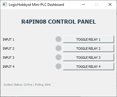
Figure 6: The custom-built PyQt5 operational interface for the R4PIN08 module.
The “Heartbeat” Logic: Why we use QTimer
In an industrial HMI application, the interface screen must constantly
scan or “poll” the PLC registers for new data. If we implement a basic, infinite loop (such as
while True), the main operating system window will lock up, freeze, and turn completely unresponsive.
Instead, we use a native QTimer. Think of this component as an accurate software metronome that
safely triggers a Modbus read event every 100 milliseconds without interfering with the responsiveness of your mouse
clicks.
What happens inside this code?
- The LED Input Logic: Every 100ms, the script reads Input Register 1 from the R4PIN08.
Python processes bits 0 to 3 using bitwise matching. If a bit is high (Active), its corresponding on-screen
indicator changes stylesheet colors instantly to
#27ae60(Green). - The Button Output Logic: Clicking an interactive button triggers an explicit Modbus
Function Code 5
write_bitcommand directly to the output addresses (Pins 4 to 7 mapped sequentially onto Modbus registers 4 to 7). - Loss of Signal Security: If your USB link is pulled or communication times out, the script catches the failure immediately and prints a prominent warning in the bottom status label.
Full Python HMI Source Code
Create a new script file inside your project directory named
main_hmi.py and drop the complete, production-ready code below into it:
import sys
import minimalmodbus
import serial
from PyQt5.QtWidgets import (QApplication, QMainWindow, QWidget, QVBoxLayout,
                             QHBoxLayout, QPushButton, QLabel, QGridLayout)
from PyQt5.QtCore import QTimer, Qt
from PyQt5.QtGui import QFont

class MiniPLCHMI(QMainWindow):
    def __init__(self):
        super().__init__()
        self.setWindowTitle("LogicHobbyist Mini-PLC Dashboard")
        self.setFixedSize(400, 320)

        # 🛠️ HARDWARE INTERFACE SPECIFIC CONFIGURATION (COM9)
        try:
            self.board = minimalmodbus.Instrument('COM9', 1)
            self.board.serial.baudrate = 9600
            self.board.serial.timeout = 0.1
            self.connected = True
        except Exception as e:
            print(f"Hardware Connection Error: {e}")
            self.connected = False

        self.init_ui()

        # ⏱️ INDUSTRIAL ENGINE HEARTBEAT (10Hz / 100ms)
        self.timer = QTimer()
        self.timer.timeout.connect(self.update_io_status)
        self.timer.start(100)

    def init_ui(self):
        main_widget = QWidget()
        self.setCentralWidget(main_widget)
        layout = QVBoxLayout()

        header = QLabel("R4PIN08 CONTROL PANEL")
        header.setFont(QFont('Inter', 14, QFont.Bold))
        header.setAlignment(Qt.AlignCenter)
        header.setStyleSheet("color: #2c3e50; margin-top: 5px; margin-bottom: 15px;")
        layout.addWidget(header)

        grid = QGridLayout()
        grid.setVerticalSpacing(12)

        # --- DIGITAL INPUTS (Pins 0 to 3 mapped to index 0-3) ---
        self.in_leds = []
        for i in range(4):
            label = QLabel(f"DIGITAL INPUT {i}")
            label.setFont(QFont('Inter', 10, QFont.Bold))
            led = QLabel()
            led.setFixedSize(18, 18)
            led.setStyleSheet("background-color: #bdc3c7; border-radius: 9px; border: 1px solid #7f8c8d;")
            grid.addWidget(label, i, 0)
            grid.addWidget(led, i, 1)
            self.in_leds.append(led)

        # --- DIGITAL OUTPUTS (Pins 4 to 7 mapped onto index 4-7) ---
        self.out_buttons = []
        for i in range(4):
            out_pin_number = i + 4
            btn = QPushButton(f"TOGGLE OUTPUT {out_pin_number}")
            btn.setFont(QFont('Inter', 9))
            btn.setCheckable(True)
            btn.setStyleSheet("background-color: #ecf0f1; padding: 6px; border: 1px solid #bdc3c7; border-radius: 4px;")
            btn.clicked.connect(lambda checked, idx=out_pin_number: self.toggle_relay(idx, checked))
            grid.addWidget(btn, i, 2)
            self.out_buttons.append(btn)

        layout.addLayout(grid)

        self.status_bar = QLabel("System Status: Ready")
        self.status_bar.setStyleSheet("font-size: 11px; color: #7f8c8d; margin-top: 15px; border-top: 1px solid #eee; padding-top: 5px;")
        layout.addWidget(self.status_bar)

        main_widget.setLayout(layout)

    def update_io_status(self):
        if not self.connected:
            self.status_bar.setStyleSheet("color: #c0392b; font-weight: bold;")
            self.status_bar.setText("System Status: HARDWARE DISCONNECTED")
            return

        try:
            # Poll Input Status Register 0x0001
            input_data = self.board.read_register(1, functioncode=3)

            # Bitwise isolation for inputs 0, 1, 2, 3
            for i in range(4):
                is_active = bool(input_data & (1 << i))
                color = "#27ae60" if is_active else "#bdc3c7"
                self.in_leds[i].setStyleSheet(f"background-color: {color}; border-radius: 9px; border: 1px solid #271a0c;")

            self.status_bar.setStyleSheet("color: #27ae60;")
            self.status_bar.setText("System Status: Online | Scan Rate 10Hz")
        except:
            self.status_bar.setStyleSheet("color: #d35400; font-weight: bold;")
            self.status_bar.setText("System Status: Modbus Polling Error")

    def toggle_relay(self, register_index, state):
        if self.connected:
            try:
                # Write state directly to specific Modbus Output index (4 to 7)
                self.board.write_bit(register_index, int(state), functioncode=5)
                color = "#e67e22; color: white; font-weight: bold;" if state else "#ecf0f1; color: black;"
                # Re-map index back to 0-3 slider context for layout selection
                layout_index = register_index - 4
                self.out_buttons[layout_index].setStyleSheet(f"background-color: {color} padding: 6px; border: 1px solid #bdc3c7; border-radius: 4px;")
            except Exception as e:
                self.status_bar.setText(f"Command Execution Failed: {e}")

if __name__ == "__main__":
    app = QApplication(sys.argv)
    window = MiniPLCHMI()
    window.show()
    sys.exit(app.exec_())
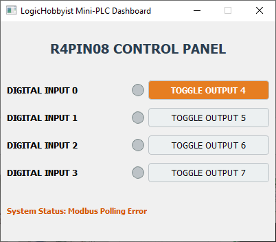
Figure 7: The custom-built PyQt5 operational interface showing error if the communication is broken.
File: main_hmi.py — Ensure your python virtual environment is actively loaded prior to execution.
Yeah! You did it! You now hold the core keys to building custom, PC-based programmable controllers. With this foundational bridge running reliably over the data link, you are equipped to scale your software automation far beyond raw toggles.
LOGICHOBBYIST PRO-TIP: The true industrial advantage of running a Python-driven PLC is Data Acquisition (DAQ). While your visual dashboard engine updates the machine indicators on your monitor frame, you can simultaneously stream every data parameter, physical toggle event, or input logic state instantly to a localized tracking sheet or a database backend without requiring high-cost vendor hardware additions!
🚀 Takeaway: Create a One-Click Desktop Launcher (.bat)
Opening the command prompt, manually navigating to your project directory, and typing the activation commands every time you want to run your HMI becomes tedious. We can automate this entire startup sequence into a simple, double-clickable desktop icon using a Windows Batch file.
C:). If your project folder resides on a secondary drive (like D:), typing a standard cd D:\folder command will fail to change your location until you explicitly instruct the terminal to swap drives by executing d: first.
Open Notepad, paste the following automation script, and save the file to your desktop as Launch_PLC.bat (ensure the file extension ends in .bat, not .txt):
@echo off
title LogicHobbyist Mini-PLC HMI Launcher

:: 1. Force Windows to switch directly to the D: drive partition
d:

:: 2. Navigate straight into your project workspace directory
cd D:\LogicHobbyist\Projects\scale-modbus

:: 3. Seamlessly activate your isolated virtual sandbox environment
call .\venv\Scripts\activate

:: 4. Fire up your custom graphical HMI engine interface
python main_hmi.py

:: 5. Keep the terminal window open if a runtime error occurs
if %errorlevel% neq 0 pause
💡 Pro Additions included in this script:
@echo off: Suppresses the background code text from flooding your terminal screen, keeping the startup presentation perfectly clean.title ...: Replaces the generic command prompt path label with a professional custom name in the taskbar window frame.call ...: Ensures the batch environment switches focus to the virtual sandbox scripts without prematurely terminating the parent terminal script wrapper execution.if %errorlevel% ... pause: A critical failsafe. If your USB-to-RS485 converter is unplugged, the app will fail to load. This line forces the terminal to stay open so you can read the Modbus connection error trace instead of letting the window instantly vanish!
🚀 Unlock the Power of Your Mini-PLC
Congratulations! You have turned a budget-friendly I/O expansion module into a fully functioning, desktop-controlled software automation panel. While these components are cheap, the combination of Modbus RTU and Python gives you capabilities that far exceed traditional hardware-bound systems.
🌐 What Can You Do Next?
By adding web-frameworks like Flask or FastAPI to your Python script, you can expose this dashboard to your local network or securely link it to a phone bot (like Telegram). You can monitor your hardware or trigger relays from absolutely anywhere in the world.
Unlike rigid programmable relays with limited memory, your PC can handle infinitely complex logic. You can program your inputs to parse third-party internet data, cross-reference data from online calendars, run mathematical algorithms, and execute time-delayed relay output scripts autonomously.
💡 Real-World Inspiration to Get Started:
- Smart Workshop Fan Management: Program a Python cron-job or script to pull local outdoor humidity data from an open weather API, and toggle your ventilation relays automatically if your indoor test bench sensor readings cross safety barriers.
- Autonomous Machine Failure Alarms: Monitor your digital inputs for machine warning loops. If an input stays active for longer than 3 seconds, instruct Python to automatically write a time-stamped log file entry to an Excel file and push an emergency warning alert to your mobile device.
- Server Rack Hardware Watchdog: Connect PC diagnostic data logs directly to the R4PIN08. If your primary computer core temperatures exceed a high threshold limit, your code can instantly trigger an output channel to force an auxiliary 12V system cooling fan to turn ON.
- Industrial Label Printing Automation: Combine this dashboard framework with our CAB Printer integration tools. When an operator triggers a physical foot-switch linked to Input 0, Python can fetch data records from a local file layout and print out a customized barcoded packing label instantly.
Great engineering isn’t about how much money you spend on the hardware—it’s about the intelligence of the code you write to manage it.